Comet 4c - Plugin Development #4
09/11/13 15:00
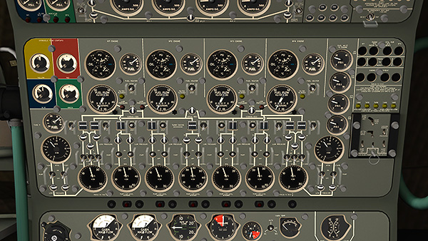
Fig. 1: Flight Engineer’s Station, Panel K (fuel system).
The plug-in programme for the fuel system is complete. The fuel panel (above) looks almost the same as it did on the original YouTube films, but it now functions properly:
Tank Cocks
X-Plane 8 could only handle three fuel tanks. X-Plane 9 could handle nine tanks, but the fuel supply controls were still only left, centre, right, or a combination of all three.
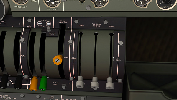
Fig. 2: Flight Engineer’s Station, Panel M (fuel distribution levers).
The Comet plug-in simulates individual fuel cocks in each tank, so that one fuel tank can be dedicated to one engine — as it needed to in the real aircraft.
Managing the weight of the aircraft was an important aspect of the Flight Engineer’s job. As it began an approach, the procedure was to have the outermost wing tanks full (tanks 4L and 4R), and all the other tanks empty. This gave the aircraft enough fuel for landing and go-around, according to the flight planning manual. The characteristic nacelle tanks (pod tanks) of the Comet 4 and 4C did not supply the engines directly, but kept tanks 4 topped up when their pumps were on.
Tanks 4L and 4R had extra cocks, maximising the choices for combining or isolating fuel lines in the event of failure. It also had three pumps per tank — double redundancy — with the third tank on an emergency bus more-or-less wired directly to the batteries.
In-Tank Pumps
The engines were started using a simple fuel suction feed. In flight, and certainly above 10,000 feet, it was essential to pressurise the fuel supply lines. In normal operation, in-tank pumps (two in each tank, supplied by different electrical buses) supplied 15 PSI pressure to the low-pressure supply circuit. This is also simulated by the plug-in, and the fuel pressure gauges register according to pressure/flow graphs in the original de Havilland training course notes.
Magnetic Indicators
As shown in the last film, Dowty three-position magnetic indicators and two-position “doll’s eyes” have been modelled and animated to show the status of all the fuel cocks and pumps.
Gauges and Warning Lamps
Fuel level gauges have a test button. Press it, and the needle will motor round in a clockwise direction, as it does in real life. Fuel low warning lights are each set to the correct level for each tank, and have a “press to test” function as well. Low fuel pressure warning lamps come on at 5.5 PSI or lower.
Fuel Heaters
The Comet Series 4 had a fuel heating system to avoid ice blocking the fuel filter — see the accident at EGLL to G-YMMM (flight BA038) on 17 January 2008. There are “filter blocked” warning lamps which come on just above JET-A waxing temperature, and engine running problems will develop if it’s ignored. Fuel heaters maintain temperature between +8 to +12 ºC when switched on.
Fuel Jettison
The safety pin and sliding panel for the fuel jettison controls worked well using standard X-Plane DataRefs, but closing the panel could not switch everything OFF at once, as it should do. The plug-in does that. It also enables the centre tank to be selected, or the wing tanks in pairs, with corresponding warning lights.
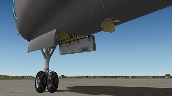
Fig. 3: Ground power access open.
Pressure Refilling
I’ve got no plans to make ground support equipment — not yet — but I have added the most important ground connections for the Comet in case I do. Fig. 3 shows the ground power access open. Inside it is the electrical supply switch for the fuel refuelling panels in the main wheel wells.
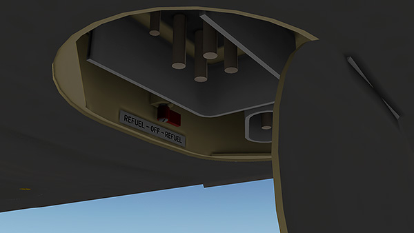
Fig. 4: Fuel refilling master switch.
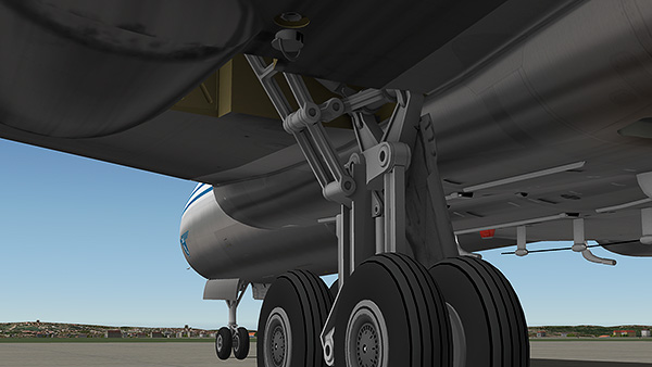
Fig. 5: The location of the fuel pressure refilling coupling, just aft of the main wheel well.

Fig. 6: The fuel pressure coupling, with cap partly removed (some texture rework required).
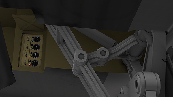
Fig. 7: The location of the fuel refilling controls for the centre and left hand tanks.
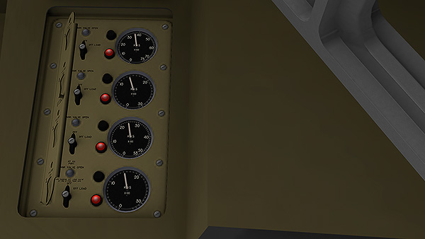
Fig. 8: Detail of the fuel refilling panel (port side).
When the master switch is on, the fuel refilling panels, gauges and panel lighting becomes live. The port side has four sets of instruments: one for the centre tank, tank 2L, 3L and 4L. The nacelle tank (pod tank) is filled via tank 4.
When the panel is live, red lamps indicate that the refuelling valves are ready, but closed, either because the switch is off or the tank is full. The switches can be used for refilling or offloading. A hinged guard prevents “off load” being selected by accident.
Next Steps
- Hydraulic System plug-in;
- HVAC plug-in;
- De-ice plug-in;
- Thorough testing;
- Documentation.
--
GMM-P (09/11/2013)
blog comments powered by Disqus