Comet 4c - Periscopic Sextant
12/02/13 18:00
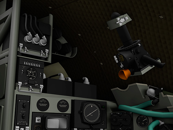
Fig. 1: Periscopic Sextant in place above the Flight Navigator’s station
Towards the end of last year, as I started compiling screen shots for the user manual, I became dissatisfied by a large blank area at the top where the escape hatch and periscopic sextant should be. So I decided to make one.
You might think a sextant only belongs on a ship, but it was a vital means of finding where an aircraft was, especially over the sea. Non pressurised aircraft had used conventional sextants, and the navigator used a domed perspex window, or “astrodome”. Pressurised jets required something more robust and streamlined.
The solution was a periscopic sextant. Henry Hughes & Sons Ltd released their first version in 1947. They were labelled "RAF Periscopic Sextant” by the military, and “Hughes” or “Kelvin Hughes” when sold commercially.
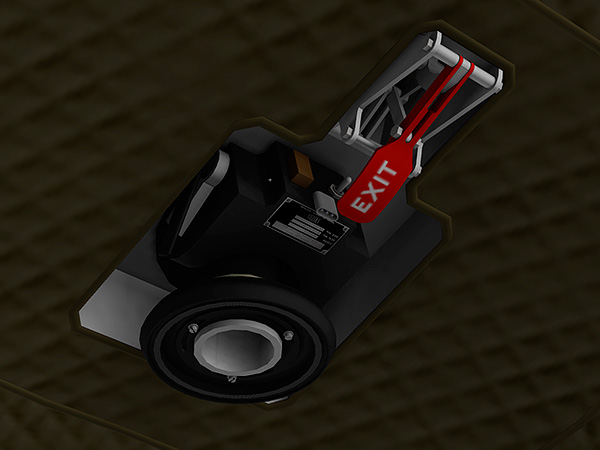
Fig. 2: The Smiths Mk. 2 Periscopic Sextant mount, fitted to the Comet 4C cockpit escape hatch.
The sextant was inserted into a mount in the roof. On the Comet Series 1-4 it was fixed directly to the roof, via a reinforced flange. On the Comet 4B and 4C it was fixed to the centre of the escape hatch in the roof. It was also used on the Canberra, Britannia, VC-10, Vulcan, and many other British aircraft.
The mount incorporated a hatch that was perfectly flush with the fuselage skin when closed, a heater to prevent the hatch from freezing up, a cylinder into which the periscope fitted, forming an airtight seal, and the cylinder was mounted on a gimbal so the sextant could be levelled, even if the aircraft was climbing.
The sextant was inserted into the mount up to a positive stop, and connected to electrical power. An interlock prevented the hatch lever from being operated unless the sextant was in place, plugging the hole, like an airlock. It would remain in this stand-by position for most of the flight, and only needed to be stowed for take-off and landing. When the navigator wanted to use the sextant, he released the interlock, pulled the lever to open the hatch, and raised the sextant to the second stop, so it was held firmly, sealed against pressure, and yet free to rotate.
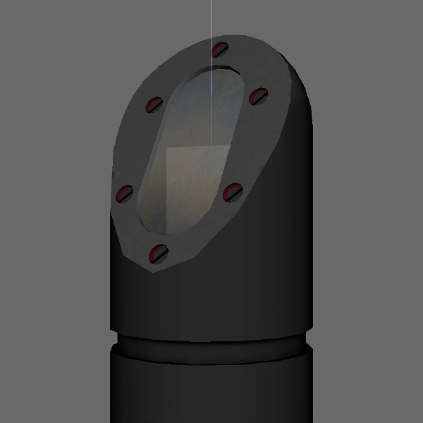
Fig. 3: The top of the periscope, showing the prism that rotated in pitch to elevate the view.
The Mk 2 periscopic sextant was an improved version with a different mount, improved gimbal and larger azimuth flange. Heating was extended to the clockwork averaging mechanism, which had run too slowly in very cold conditions. British military versions were branded “RAF”. Civilian versions of the Mk 2 were branded "Smiths".
A traditional sextant has a split optical view of the horizon and the sun (or other celestial body). The Hughes Periscopic Sextant dispensed with the view of the horizon, instead superimposing the image of an internal bubble level on the view out through the periscope. Because the bubble would change in size with the aircraft’s internal pressure, the bubble had to be adjusted to the correct size by the operator during the set-up process. During the day, the edge of the bubble was seen in silhouette — a black ring. At night, two light sources were focused on the bubble chamber, the bubble itself acting as a lens, and these lights appeared as two red pin-prick lights in the viewfinder. The sextant was perfectly aligned when the sun and the bubble’s visible ring were on top of each other, or a star was exactly between the two red lights.
To operate the periscope, the navigator first swung the sextant round to the approximate bearing to find the celestial body, selected an appropriate filter (dark for the sun) and raised the view by inclining a prism at the top of the persicope using the coarse inclination knob on the top right of the machine. This knob clicked in 10 degree intervals from -10 to +80 degrees. Having found the target approximately, the navigator would then level the sextant, arranging the bubble in the middle of a circular graticule by swinging the assembly on the gimbal.
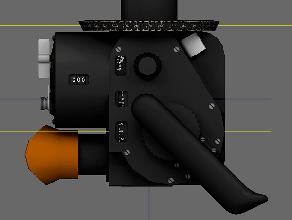
Fig. 4: Left hand side elevation, showing the average scale on the cylindrical part of the body, and three instantaneous scales on the main part of the body. The top scale measured coarse elevation from -10 to +80 in 10 degree intervals, the middle scale measured fine elevation in degrees, and the bottom scale in minutes. The top knob (next to the coarse scale) was for setting coarse elevation. The large wheel forming part of the right hand grip was for fine adjustment. (The yellow lines on the illustration are construction lines, and nothing to do with the original instrument).
For an instantaneous reading, the navigator would use the fine adjustment knob to bring the celestial body into view, so it coincided with the bubble and the circle. Then he'd take a note of the time, lock the periscope off, read the scales on the side of the machine, and cross-reference the reading with the sight reduction tables.
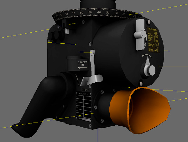
Fig. 5: Left rear view showing (from left to right) an illumination dimmer knob as part of the left hand grip, the azimuth (heading) lock on the azimuth scale, a thumbwheel to introduce neutral density filters to shade the view in bright sunlight, the averaging trigger. Then, on the back of the cylinder, the clockwork winder and time selector for the averaging mechanism.
As well as taking instantaneous readings, the machine could take 60 measurements over period of either 1 or 2 minutes, and calculate the average. The mechanism was clockwork. It was wound up, then released with a trigger near the left hand grip. While the timer was running, the operator had to keep the celestial body in the bubble, and the bubble in the circle.
The averaging mechanism and the fine inclination adjustment only operated over a 13º30' range, so the coarse adjustment was always necessary first. The navigator would have to read the coarse scale, then add either the instantaneous scale readings or the average scale reading to it to calculate the total inclination.
Maintaining a bubble was a nuisance, so a further development, the Mk 2A, replaced the bubble assembly with a glass disc, etched like an artificial horizon. This was suspended on a pendulum. It saved time for the navigator, and was much easier to illuminate and display in all conditions, day or night. There were other versions too, some with longer periscopes, another Mk. 2T designed for very, very high altitude.
Fig 6: Diagram illustrating the observed view through a Smiths Mk.2A Periscopic Sextant.
The ambition is to create a proper simulation of the Smiths Mk. 2A Periscopic Sextant, which would return a bearing and an angle of elevation and leave the rest up to the user. It may (or may not) be possible … I will report progress!
--
GMM-P (12/02/2013)
blog comments powered by Disqus