Comet 4c - Stall Test Results
14/03/16 23:00
When calibrating the performance of the Comet 4C model, everything starts with a stall test. Stalls in clean configuration allow me to adjust the aerofoils for the right amount of lift. Once that's set, I can move on to other aspects of performance.
Stall tests by de Havilland were carried out at 10,000 feet, with throttles closed. The stall was defined as the moment the aircraft could not maintain 1.00g normal to the flight path. This avoided the aircraft actually dropping a wing, or otherwise over-stressing the airframe. Instantaneous readings were taken using a Royal Aircraft Establishment (Smith Barnes) accelerometer, which had an accuracy of 1%.
For the X-Plane stall-test plug-in, I used a PID controller to maintain a constant vertical path of zero (level flight). As the Comet model approached the stall, the rate of change of lift was too quick for the PID controller to keep up with. The controller was tuned to respond as rapidly as possible, without surging or noise, but the flight path still curved down prematurely. I had to find some way to allow for this.
The test was also set up to record the angle of attack, which I could compare with the maximum angle of lift for the aerofoils: Alpha(MAX). Consistently, this happened when the vertical force = 0.99 g, so I have used this as my offset in the table of results, below. An accuracy of 1%, repeatable time after time, is an awful lot better than I was achieving manually!
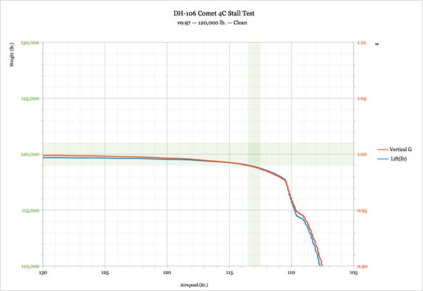
Fig.1: Lift and vertical acceleration against indicated airspeed during a stall.
The green bands are the figures for the real Comet 4C, as targets with a 1% tolerance.
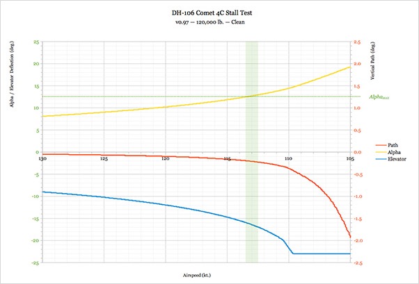
Fig.2: Vertical flight path, angle of attack and elevator angle during a stall. Maximum lift is achieved when the yellow curve intersects the dotted green line at "Alpha(MAX)" (12.5 degrees) as shown. The elevators reach maximum travel at -23 degrees, shown by the blue line.
Fig.3: Table of stall results for a range of weights (updated for X-Plane 10.45 on 30/06/2016)
Aerofoil settings are a compromise between low and high weights. These figures were achieved using Javafoil to calculate lift for a NACA 63A011 + 8.0%, which is realistic for a wing with modest leading edge droop.
Next step: Verify that there is sufficient lift using a take-off test plug-in.
--
GMM-P
(14-03-2016)
Stall tests by de Havilland were carried out at 10,000 feet, with throttles closed. The stall was defined as the moment the aircraft could not maintain 1.00g normal to the flight path. This avoided the aircraft actually dropping a wing, or otherwise over-stressing the airframe. Instantaneous readings were taken using a Royal Aircraft Establishment (Smith Barnes) accelerometer, which had an accuracy of 1%.
For the X-Plane stall-test plug-in, I used a PID controller to maintain a constant vertical path of zero (level flight). As the Comet model approached the stall, the rate of change of lift was too quick for the PID controller to keep up with. The controller was tuned to respond as rapidly as possible, without surging or noise, but the flight path still curved down prematurely. I had to find some way to allow for this.
The test was also set up to record the angle of attack, which I could compare with the maximum angle of lift for the aerofoils: Alpha(MAX). Consistently, this happened when the vertical force = 0.99 g, so I have used this as my offset in the table of results, below. An accuracy of 1%, repeatable time after time, is an awful lot better than I was achieving manually!
Fig.1: Lift and vertical acceleration against indicated airspeed during a stall.
The green bands are the figures for the real Comet 4C, as targets with a 1% tolerance.
Fig.2: Vertical flight path, angle of attack and elevator angle during a stall. Maximum lift is achieved when the yellow curve intersects the dotted green line at "Alpha(MAX)" (12.5 degrees) as shown. The elevators reach maximum travel at -23 degrees, shown by the blue line.
| Aerofoils | Weight | Flap | U/C | Elevator | Alpha | Target | Actual | Accuracy |
| Mod | Lbs | Degrees | Up/Down | Degrees | Degrees | Speed (kt.) | Speed (kt.) | |
127 | 100,000 | 0 | UP | 17.2 | 12.3 | 103.0 | 103.5 | 0.5% |
| 127 | 100,000 | 20 | UP | 22.9 | 11.2 | 98.0 | 98.9 | 0.9% |
| 127 | 100,000 | 40 | DOWN | 20.8 | 9.8 | 93.0 | 95.0 | 2.2% |
127 | 120,000 | 0 | UP | 16.5 | 12.3 | 113.0 | 113.0 | 0.0% |
| 127 | 120,000 | 20 | UP | 21.8 | 11.2 | 107.0 | 107.8 | 0.7% |
| 127 | 120,000 | 40 | DOWN | 18.9 | 9.7 | 102.0 | 103.6 | 1.6% |
127 | 140,000 | 0 | UP | 16.0 | 12.4 | 123.0 | 121.5 | -1.2% |
| 127 | 140,000 | 20 | UP | 21.2 | 11.3 | 116.0 | 116.0 | 0.0% |
| 127 | 140,000 | 40 | DOWN | 18.7 | 10.1 | 110.0 | 111.0 | 0.9% |
127 | 160,000 | 0 | UP | 15.7 | 12.4 | 133.0 | 129.6 | -2.6% |
| 127 | 160,000 | 20 | UP | 20.9 | 11.4 | 125.0 | 123.6 | -1.1% |
| 127 | 160,000 | 40 | DOWN | 18.2 | 10.2 | 118.0 | 118.3 | 0.3% |
Aerofoil settings are a compromise between low and high weights. These figures were achieved using Javafoil to calculate lift for a NACA 63A011 + 8.0%, which is realistic for a wing with modest leading edge droop.
Next step: Verify that there is sufficient lift using a take-off test plug-in.
--
GMM-P
(14-03-2016)
blog comments powered by Disqus